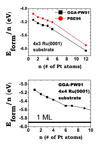
Average formation energy per atom, Eform=n, as a function of the size, n, of the island for n = 1 – 5 on the (3×4) supercell (upper panel) and for n =1 – 4, 6, 7, and 9 on the (4×4) supercell (lower panel). Figure taken from Phys. Rev. B 79, 125432 (2009)
[Phys. Rev. B 78, 195417 (2008) and J. Phys.: Condens. Matter 21, 474226 (2009)] This work focuses on understanding the performance of clean energy conversion nanodevices, proton exchange membrane fuel cells (PEMFCs) in particular. Operation of the anode in these devices consists of splitting hydrogen molecules into protons and electrons and Pt atoms on the anode catalyze such process. Unfortunately, the main source of hydrogen is hydrocarbons, which unavoidably contain carbon monoxide (CO) molecules. CO molecules are undesirable because they severely poison the reactivity of commercially used anodes as they sit on the Pt sites and block them as a result. In the recent past, a new PEMFCs anode was developed and, surprisingly, its reactivity was much less sensitive to the presence of CO.
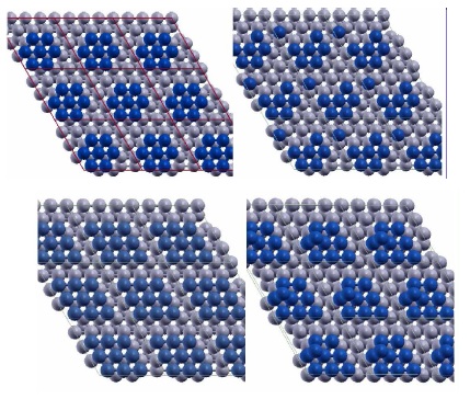
(Top) Two configurations of a 7-atom Pt island (blue) on Ru(0001) (grey) showing the detachment of one Pt atom. The configuration in the right panel has lower Eform=n than the configuration in the left panel by 0.14 eV. (Bottom) Two configurations of a 9-atom Pt island (blue) with 2D(left) and 3D(right) structure on Ru(0001) (grey) used in calculations. Figure taken from Phys. Rev. B 79, 125432 (2009)
The preparation of such device had given only some clues about the particulars of its structure. The novel anode was in fact a set Ru particles of few nanometers sprinkled with small amounts of Pt. However, in order to understand the mechanism by which this device copes with the above-mentioned traces of CO, it was essential to investigate the details of the atomic arrangement at the surface of the anode. In reference [1], total energy calculations allowed us to reveal that Pt atoms tend to form two-dimensional islands on Ru, instead of three-dimensional ones. This, in turn, pushed forward an earlier idea: that the enhanced activity of the novel anode was because somehow the undesired CO molecules do not stay on the Pt sites but migrate to Ru ones. Sure enough, in reference [2] we showed that the atoms forming the 2D islands displayed an electronic-structure profile such that, if a CO molecule somehow reaches the Pt island, it tends to abandon it to reduce the total energy of the system. Moreover, we demonstrated that CO in fact does not stay on Ru sites. Once it reaches the edge of the island, it actually reacts with another molecule commonly present in the reaction environment, OH, oxidizes forming CO2 and desorbs in the gas form.
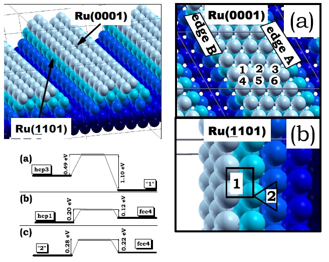
Model of the edges of a faceted Ru nanoparticle exposing a (0001) facet and two (¹1101) facets. Different colors distinguish the five layers parallel to the (0001) surface constituting the structure. Adsorption sites of Pt monomers (red) on the (0001) facet of the Ru nanoparticle model (blue). Numbers “1”, “2” and “3” indicate hcp sites and “4”, “5”, “6” indicate fcc sites. (b) Adsorption sites of Pt monomers on the (-1101) facets of the Ru nanoparticle model. Numbers “1” and “2” indicate four-fold and three-fold hollow sites, respectively. Also shown, the energy barrier for the diffusion of a Pt monomer (a) across the edge A. Figure taken from Phys. Rev. B 79, 125432 (2009)
Still, it remained toexplain how few-atom Pt islands could remain as such without aggregating into one big single island, which actually would significantly lower the energy. An analysis of the size, structure and preparation of the Pt-loaded Ru nanoparticles led us to the answer. The anode is prepared in such a way that the Pt atoms were distributed on the many facets of the Ru nanoparticles. We showed that, although diffusion within a particular island is easily activated at room temperature, the Pt atoms are trapped in the facet they are initially adsorbed on unless they overcome very large energy barriers to diffuse from facet to facet. In this way, we showed that the smallness and faceting of the Ru nanoparticles is an essential factor that allows Pt to remain as small 2D islands, the key feature of the anode that makes Pt protected from CO poisoning.
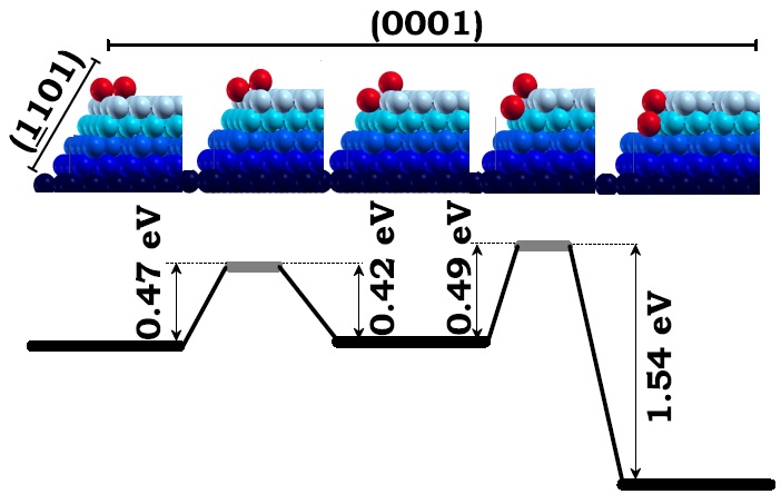
The upper five panels from left to right illustrate the two-step diffusion of the dimmer (red) across the edge intersecting the (0001) and the (-1101) facets (blue). First, third, and fifth upper panels are local minimum energy configurations of the dimmer and the second and forth upper panels are transition states. The lower panel shows the barrier for the dimmer to diffuse back and forth from either local minimum energy configuration. Figure taken from Phys. Rev. B 79, 125432 (2009)
References:
[1] M. Alcántara Ortigoza, S. Stolbov, and T. S. Rahman; “Formation of Pt islets on facets of Ru nanoparticles: First-principles study“; Phys. Rev. B 78, 195417 (2008)
[2] S. Stolbov, M. Alcántara Ortigoza, and T. S. Rahman; “Application of the density functional theory to the fuel cell problem“; J. Phys.: Condens. Matter 21, 474226 (2009)